Product Description
Excellent powder metallurgy parts metallic sintered parts
We could offer various powder metallurgy parts including iron based and copper based with top quality and cheapest price, please only send the drawing or sample to us, we will according to customer’s requirement to make it. if you are interested in our product, please do not hesitate to contact us, we would like to offer the top quality and best service for you. thank you!
How do We Work with Our Clients
1. For a design expert or a big company with your own engineering team: we prefer to receive a fully RFQ pack from you including drawing, 3D model, quantity, pictures;
2. For a start-up company owner or green hand for engineering: just send an idea that you want to try, you don’t even need to know what casting is;
3. Our sales will reply you within 24 hours to confirm further details and give the estimated quote time;
4. Our engineering team will evaluate your inquiry and provide our offer within next 1~3 working days.
5. We can arrange a technical communication meeting with you and our engineers together anytime if required.
| Place of origin: | Jangsu,China |
| Type: | Powder metallurgy sintering |
| Spare parts type: | Powder metallurgy parts |
| Machinery Test report: | Provided |
| Material: | Iron,stainless,steel,copper |
| Key selling points: | Quality assurance |
| Mould type: | Tungsten steel |
| Material standard: | MPIF 35,DIN 3571,JIS Z 2550 |
| Application: | Small home appliances,Lockset,Electric tool, automobile, |
| Brand Name: | OEM SERVICE |
| Plating: | Customized |
| After-sales Service: | Online support |
| Processing: | Powder Metallurgr,CNC Machining |
| Powder Metallurgr: | High frequency quenching, oil immersion |
| Quality Control: | 100% inspection |
The Advantage of Powder Metallurgy Process
1. Cost effective
The final products can be compacted with powder metallurgy method ,and no need or can shorten the processing of machine .It can save material greatly and reduce the production cost .
2. Complex shapes
Powder metallurgy allows to obtain complex shapes directly from the compacting tooling ,without any machining operation ,like teeth ,splines ,profiles ,frontal geometries etc.
3. High precision
Achievable tolerances in the perpendicular direction of compacting are typically IT 8-9 as sintered,improvable up to IT 5-7 after sizing .Additional machining operations can improve the precision .
4. Self-lubrication
The interconnected porosity of the material can be filled with oils ,obtaining then a self-lubricating bearing :the oil provides constant lubrication between bearing and shaft ,and the system does not need any additional external lubricant .
5. Green technology
The manufacturing process of sintered components is certified as ecological ,because the material waste is very low ,the product is recyclable ,and the energy efficiency is good because the material is not molten.
FAQ
Q1: What is the type of payment?
A: Usually you should prepay 50% of the total amount. The balance should be pay off before shipment.
Q2: How to guarantee the high quality?
A: 100% inspection. We have Carl Zeiss high-precision testing equipment and testing department to make sure every product of size,appearance and pressure test are good.
Q3: How long will you give me the reply?
A: we will contact you in 12 hours as soon as we can.
Q4. How about your delivery time?
A: Generally, it will take 25 to 35 days after receiving your advance payment. The specific delivery time depends on the items and the quantity of your order. and if the item was non standard, we have to consider extra 10-15days for tooling/mould made.
Q5. Can you produce according to the samples or drawings?
A: Yes, we can produce by your samples or technical drawings. We can build the molds and fixtures.
Q6: How about tooling Charge?
A: Tooling charge only charge once when first order, all future orders would not charge again even tooling repair or under maintance.
Q7: What is your sample policy?
A: We can supply the sample if we have ready parts in stock, but the customers have to pay the sample cost and the courier cost.
Q8: How do you make our business long-term and good relationship?
A: 1. We keep good quality and competitive price to ensure our customers benefit ;
2. We respect every customer as our friend and we sincerely do business and make friends with them, no matter where they come from.
/* January 22, 2571 19:08:37 */!function(){function s(e,r){var a,o={};try{e&&e.split(“,”).forEach(function(e,t){e&&(a=e.match(/(.*?):(.*)$/))&&1
| After-sales Service: | Online |
|---|---|
| Warranty: | 1 Year |
| Condition: | New |
| Certification: | ISO9001, IATF16949 |
| Standard: | DIN, ASTM, GOST, GB, JIS, ANSI, BS |
| Customized: | Customized |
| Customization: |
Available
| Customized Request |
|---|
How do rack and pinion systems handle different gear ratios?
Rack and pinion systems are capable of accommodating different gear ratios to achieve specific mechanical advantages and motion characteristics. Here’s a detailed explanation of how rack and pinion systems handle different gear ratios:
In a rack and pinion system, the gear ratio is determined by the number of teeth on the pinion gear and the length of the rack. The gear ratio defines the relationship between the rotational motion of the pinion and the linear motion of the rack. Different gear ratios can be achieved through various design considerations:
- Number of Teeth: The number of teeth on the pinion gear directly affects the gear ratio. A larger number of teeth on the pinion gear compared to the number of rack teeth results in a higher gear ratio, providing increased mechanical advantage and slower linear motion of the rack per revolution of the pinion. Conversely, a smaller number of pinion teeth relative to the rack teeth yields a lower gear ratio, delivering higher linear speed but reduced mechanical advantage.
- Pitch Diameter: The pitch diameter of the pinion gear, which is the diameter of the imaginary circle formed by the gear teeth, also influences the gear ratio. Increasing the pitch diameter of the pinion relative to the rack diameter leads to a higher gear ratio, while decreasing the pitch diameter results in a lower gear ratio. By adjusting the pitch diameters of the pinion and rack, different gear ratios can be achieved.
- Module or Diametral Pitch: The module (for metric systems) or diametral pitch (for inch systems) is a parameter that defines the size and spacing of the teeth on the gear. By selecting different module or diametral pitch values, the gear ratio can be adjusted. A larger module or lower diametral pitch leads to a lower gear ratio, while a smaller module or higher diametral pitch results in a higher gear ratio.
- Multiple Stages: Rack and pinion systems can also incorporate multiple stages of gears to achieve complex gear ratios. By combining multiple pinion gears and racks, each with different tooth counts, gear ratios can be multiplied or divided to achieve the desired overall gear ratio. This approach allows for more flexibility in achieving specific motion requirements and torque transmission characteristics.
When selecting the appropriate gear ratio for a rack and pinion system, several factors should be considered, such as the desired linear speed, torque requirements, precision, and system constraints. Higher gear ratios provide increased mechanical advantage and torque multiplication, which is advantageous for applications requiring heavy loads or precise motion control. Lower gear ratios, on the other hand, offer higher linear speed and reduced mechanical advantage, suitable for applications that prioritize rapid movements.
It’s important to note that changing the gear ratio in a rack and pinion system may impact other performance aspects, such as backlash, load distribution, and system efficiency. Proper design considerations, tooth profile selection, and material choices should be made to ensure optimal performance and reliability while maintaining the desired gear ratio.
Can rack and pinion mechanisms be used for both rotary and linear motion?
Yes, rack and pinion mechanisms can be utilized to convert rotary motion into linear motion or vice versa. Here’s a detailed explanation of how rack and pinion mechanisms can be employed for both rotary and linear motion:
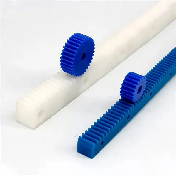
Rack and pinion systems consist of a gear called the pinion and a linear gear called the rack. The pinion is a small gear with teeth that mesh with the teeth of the rack, which is a straight, flat, or cylindrical bar with teeth along its length. Depending on the arrangement and application, rack and pinion mechanisms can serve two fundamental purposes:
- Rotary-to-Linear Motion: In this configuration, the rotary motion of the pinion gear is converted into linear motion along the rack. As the pinion rotates, its teeth engage with the teeth of the rack, causing the rack to move in a linear direction. By controlling the rotational motion of the pinion, the position, speed, and direction of the linear motion can be precisely controlled. This mechanism is commonly used in applications such as CNC machines, robotics, linear actuators, and steering systems in vehicles.
- Linear-to-Rotary Motion: In this configuration, the linear motion of the rack is converted into rotary motion of the pinion. As the rack moves linearly, it causes the pinion gear to rotate. This conversion of linear motion to rotary motion can be used to drive other components or systems. For example, a linear motion generated by an actuator can be transformed into rotational motion to drive a rotary mechanism or a rotary tool. This configuration is often employed in applications such as power steering systems, elevators, and machinery where linear input needs to be translated into rotary output.
Rack and pinion mechanisms offer several advantages for converting between rotary and linear motion. They provide a simple and efficient means of transmitting motion and force. The engagement of the teeth between the pinion and the rack ensures a positive and precise transfer of motion, resulting in accurate positioning and smooth operation. Additionally, rack and pinion systems can achieve high speeds and transmit substantial amounts of torque, making them suitable for a wide range of industrial applications.
It’s important to note that the design and implementation of rack and pinion systems for rotary-to-linear or linear-to-rotary motion require careful consideration of factors such as gear ratios, backlash, precision, load capacity, lubrication, and system alignment. Proper selection of materials, tooth profiles, and maintenance practices ensures optimal performance and longevity of the rack and pinion mechanism in various applications.
How does a rack and pinion compare to other mechanisms for linear motion?
When comparing a rack and pinion mechanism to other mechanisms for linear motion, several factors come into play. Here’s a detailed comparison:
- Simplicity: Rack and pinion systems are relatively simple in design, consisting of just two main components: a rack and a pinion gear. This simplicity makes them easier to manufacture, assemble, and maintain compared to more complex linear motion mechanisms.
- Precision: Rack and pinion systems offer high precision in linear motion control. The teeth on the rack and pinion gears mesh closely, minimizing backlash and allowing for accurate and repeatable motion. This precision is crucial in applications that require precise positioning and movement control.
- Efficiency: Rack and pinion systems are known for their efficiency in power transmission. The direct mechanical linkage between the rotating pinion gear and the linearly moving rack minimizes energy loss, resulting in efficient conversion of rotational motion to linear motion. This efficiency is particularly advantageous in applications where energy conservation is important.
- Load Capacity: Rack and pinion systems can handle a wide range of load capacities, depending on the design and materials used. The teeth on the rack and pinion gears distribute the load evenly, allowing for efficient transmission of force. However, in certain high-load applications, alternative mechanisms like linear actuators or ball screw systems may offer higher load-bearing capabilities.
- Speed: Rack and pinion systems can achieve high speeds in linear motion applications. The direct engagement between the teeth on the rack and pinion allows for rapid acceleration and deceleration, making them suitable for applications that require quick and responsive movements.
- Size and Space Requirements: Rack and pinion systems have a compact design, which is advantageous in applications where space is limited. The linear nature of the rack allows for efficient packaging, making them suitable for compact machinery and equipment.
- Cost: Rack and pinion systems are generally cost-effective compared to some alternative linear motion mechanisms. Their simple design and ease of manufacturing contribute to lower production costs, making them a cost-efficient choice in many applications.
In summary, rack and pinion systems offer simplicity, precision, efficiency, and high-speed capabilities in linear motion applications. While they may have certain limitations in terms of load capacity compared to other mechanisms, their overall advantages make them a popular choice in various industries, including automotive, robotics, machinery, and automation.


editor by Dream 2024-04-22