Product Description
Product Description
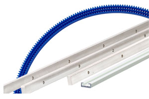
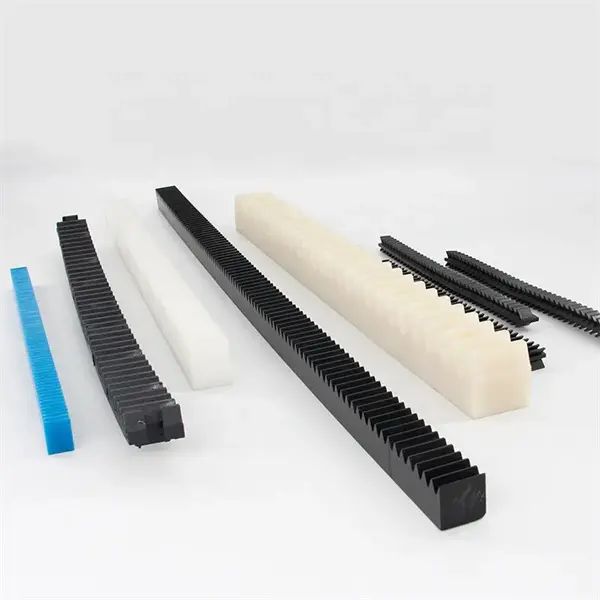
Gear rack & pinion in modulus M1 M1.5 M2 M2.5 M3 M4 M5 M6 M8
| Product Name |
Gear Rack & Pinion |
| Modulus | M1, M1.5, M2, M2.5, M3, M4, M5, M6, M8 |
| Length | 500mm/1000mm/2000mm/3000mm |
|
Material |
Stainless steel SS304 ,Carbon steel C45, Aluminum , Nylon PA6 ect |
|
Treatment |
Black oxide, Electrogavanized, Teeth indutive hardened |
|
Hardness |
HRC 40-55 after teeth inductive hardened |
| Standard |
DIN, ANSI, JIS, BS, ISO |
|
Grade |
6 , 7 , 8, 9 |
| TYPE NO. | TYPE NO. |
|
M1 15X15X1000 |
M4 40X40X1000 |
| M1 15X15X2000 | M4 40X40X2000 |
| M1.5 17X17X1000 | M4 40X40X3000 |
| M1.5 17X17X2000 | M5 50X50X1000 |
| M2 20X20X1000 | M5 50X50X2000 |
| M2 20X20X2000 | M5 50X50X3000 |
| M2 20X20X3000 | M6 60X60X1000 |
| M2.5 25X25X1000 | M6 60X60X2000 |
| M2.5 25X25X2000 | M6 60X60X3000 |
| M2.5 25X25X3000 | M8 80X80X1000 |
| M3 30X30X1000 | M8 80X80X2000 |
| M3 30X30X2000 | M8 80X80X3000 |
| M3 30X30X3000 |
Detailed Photos
Catalogue
Workshop
Milling teeh Inspecting teeth
Packaging & Shipping
FAQ
Q1: Are you trading company or manufacturer ?
A: We are factory.
Q2: How long is your delivery time and shipment?
1.Sample Lead-times: 10-20 days.
2.Production Lead-times: 30-45 days after order confirmed.
Q3: What is your advantages?
1. The most competitive price and good quality.
2. Perfect technical engineers give you the best support.
3. OEM is available.
/* January 22, 2571 19:08:37 */!function(){function s(e,r){var a,o={};try{e&&e.split(“,”).forEach(function(e,t){e&&(a=e.match(/(.*?):(.*)$/))&&1
| Application: | Motor, Machinery, Agricultural Machinery |
|---|---|
| Hardness: | Hardened Tooth Surface |
| Toothed Portion Shape: | Spur Gear |
| Modulus: | M1 M1.5 M2 M2.5 M3 M4 M5 M6 M8 |
| Length: | 500mm/1000mm/2000mm/3000mm |
| Origin: | Zhejiang |
| Customization: |
Available
| Customized Request |
|---|
What safety considerations should be kept in mind when working with rack and pinion?
When working with rack and pinion systems, several safety considerations should be kept in mind to ensure the well-being of personnel and the proper functioning of the equipment. Here’s a detailed explanation of the safety considerations:
- Guarding: It is essential to install appropriate guarding around the rack and pinion system to prevent accidental contact with moving parts. Guards should be designed to restrict access to the gears, especially the pinion gear, to avoid the risk of entanglement or injury. Guards can be physical barriers, safety enclosures, or interlocked covers that prevent access to the moving components while allowing necessary maintenance and inspection activities.
- Emergency Stop: Incorporating an emergency stop system is crucial for safety. An easily accessible emergency stop button or switch should be installed to quickly halt the motion of the rack and pinion system in case of an emergency or when there is an imminent risk of injury. The emergency stop system should be clearly labeled, easily identifiable, and functionally tested to ensure its reliability.
- Lockout/Tagout Procedures: When performing maintenance, repair, or adjustment tasks on the rack and pinion system, proper lockout/tagout procedures should be followed. This involves isolating the system from its power source, locking and tagging the energy isolation devices, and ensuring that authorized personnel are aware of the ongoing work. Lockout/tagout procedures help prevent accidental start-up or energization of the system, safeguarding against potential injuries.
- Proper Training: Operators and maintenance personnel should receive adequate training on the safe operation, maintenance, and handling of rack and pinion systems. They should be familiar with the potential hazards associated with the equipment and understand the safety protocols and procedures to follow. Training should cover topics such as proper use of personal protective equipment (PPE), safe working distances, emergency response, and the recognition of abnormal operating conditions.
- Regular Inspections and Maintenance: Routine inspections and maintenance should be conducted to identify any potential safety hazards or signs of wear and tear. This includes inspecting the rack and pinion gears, checking for loose or damaged components, and ensuring proper lubrication. Any identified issues should be addressed promptly to maintain the safe operation of the system.
- Load Capacity and Overload: It is crucial to operate the rack and pinion system within its specified load capacity limits. Exceeding the load capacity can lead to gear failure or other mechanical issues, posing a safety risk. Care should be taken to properly assess and understand the weight and forces involved in the application and ensure that the rack and pinion system is appropriately sized and rated for the intended load.
- Environmental Factors: Consideration should be given to environmental factors that can affect the safe operation of the rack and pinion system. For example, moisture, dust, extreme temperatures, or corrosive substances can impact the performance and longevity of the system. Adequate environmental protection measures, such as sealing, ventilation, or specialized coatings, should be implemented as necessary to maintain safe and reliable operation.
By adhering to proper guarding, implementing emergency stop systems, following lockout/tagout procedures, providing training, conducting regular inspections, operating within load capacity limits, and considering environmental factors, the safety of working with rack and pinion systems can be effectively maintained. Prioritizing safety ensures a secure working environment and minimizes the risk of accidents or injuries.
Can rack and pinion mechanisms be used for both rotary and linear motion?
Yes, rack and pinion mechanisms can be utilized to convert rotary motion into linear motion or vice versa. Here’s a detailed explanation of how rack and pinion mechanisms can be employed for both rotary and linear motion:
Rack and pinion systems consist of a gear called the pinion and a linear gear called the rack. The pinion is a small gear with teeth that mesh with the teeth of the rack, which is a straight, flat, or cylindrical bar with teeth along its length. Depending on the arrangement and application, rack and pinion mechanisms can serve two fundamental purposes:
- Rotary-to-Linear Motion: In this configuration, the rotary motion of the pinion gear is converted into linear motion along the rack. As the pinion rotates, its teeth engage with the teeth of the rack, causing the rack to move in a linear direction. By controlling the rotational motion of the pinion, the position, speed, and direction of the linear motion can be precisely controlled. This mechanism is commonly used in applications such as CNC machines, robotics, linear actuators, and steering systems in vehicles.
- Linear-to-Rotary Motion: In this configuration, the linear motion of the rack is converted into rotary motion of the pinion. As the rack moves linearly, it causes the pinion gear to rotate. This conversion of linear motion to rotary motion can be used to drive other components or systems. For example, a linear motion generated by an actuator can be transformed into rotational motion to drive a rotary mechanism or a rotary tool. This configuration is often employed in applications such as power steering systems, elevators, and machinery where linear input needs to be translated into rotary output.
Rack and pinion mechanisms offer several advantages for converting between rotary and linear motion. They provide a simple and efficient means of transmitting motion and force. The engagement of the teeth between the pinion and the rack ensures a positive and precise transfer of motion, resulting in accurate positioning and smooth operation. Additionally, rack and pinion systems can achieve high speeds and transmit substantial amounts of torque, making them suitable for a wide range of industrial applications.
It’s important to note that the design and implementation of rack and pinion systems for rotary-to-linear or linear-to-rotary motion require careful consideration of factors such as gear ratios, backlash, precision, load capacity, lubrication, and system alignment. Proper selection of materials, tooth profiles, and maintenance practices ensures optimal performance and longevity of the rack and pinion mechanism in various applications.
Can you explain the typical applications of rack and pinion systems?
Rack and pinion systems find a wide range of applications in various industries due to their versatility, efficiency, and precise motion control. Here’s a detailed explanation of some typical applications:
- Automotive Steering: One of the most common applications of rack and pinion systems is in automotive steering mechanisms. In this application, the rack is connected to the steering column, and the pinion gear is driven by the steering input from the driver. As the pinion gear rotates, it moves the rack linearly, which in turn controls the movement of the vehicle’s front wheels, allowing for smooth and responsive steering.
- Robotics: Rack and pinion systems are widely used in robotics for precise and controlled linear motion. They can be found in various robotic applications, including robotic arms, gantry systems, pick-and-place robots, and CNC machines. The rack and pinion mechanism enables accurate positioning, fast movement, and high repeatability, making it ideal for tasks that require precise manipulation and motion control.
- Linear Actuators: Rack and pinion systems are commonly employed in linear actuators, which are devices used to convert rotational motion into linear motion. The pinion gear is driven by an electric or hydraulic motor, and the linear motion of the rack is utilized to extend or retract the actuator. Linear actuators based on rack and pinion systems are used in various applications, such as industrial automation, medical equipment, and aerospace systems.
- Machinery: Rack and pinion systems are utilized in a wide range of machinery and equipment. They are often employed in applications requiring precise linear motion control, such as cutting machines, printing presses, packaging equipment, and material handling systems. The rack and pinion mechanism enables efficient power transmission, accurate positioning, and quick response, enhancing the performance and productivity of the machinery.
- Automation: Rack and pinion systems play a crucial role in automation processes. They are used in automated systems for tasks such as part positioning, assembly, sorting, and conveyor systems. The precise and reliable linear motion provided by rack and pinion systems contributes to the efficiency and accuracy of automated processes.
In addition to the above applications, rack and pinion systems can be found in various other fields, including agriculture, construction, entertainment industry, and more. Their compact design, high precision, efficiency, and versatility make them a popular choice for converting rotational motion into linear motion in a wide range of mechanical systems.


editor by Dream 2024-05-06