Product Description
Product Description
| Product Name | 56500-1W100 Steering Rack and Pinion For CZPT ACCENT / CZPT RIO III |
| Application | HYUNDAI ACCENT / CZPT RIO III Automobile Steering system |
| OEM NO |
56500-1W100 |
| Car Make | HYUNDAI ACCENT / CZPT RIO III |
| Warranty | 12 Months |
| Weight | 7KG |
| Drive Xihu (West Lake) Dis. | LHD |
| Type | Mechanical-Electric |
| ZUA NO | F-HU-056 |
Our Advantages
Company Profile
Exhibition
| After-sales Service: | 24-Hour on-Line |
|---|---|
| Warranty: | 12 Months |
| Type: | Steering Rack |
| Material: | Metal and Plastic |
| Certification: | ISO, IATF16949 |
| Automatic: | Mechanical-Electric |
| Samples: |
US$ 399/Piece
1 Piece(Min.Order) | |
|---|
| Customization: |
Available
| Customized Request |
|---|
How do rack and pinion systems handle different gear ratios?
Rack and pinion systems are capable of accommodating different gear ratios to achieve specific mechanical advantages and motion characteristics. Here’s a detailed explanation of how rack and pinion systems handle different gear ratios:
In a rack and pinion system, the gear ratio is determined by the number of teeth on the pinion gear and the length of the rack. The gear ratio defines the relationship between the rotational motion of the pinion and the linear motion of the rack. Different gear ratios can be achieved through various design considerations:
- Number of Teeth: The number of teeth on the pinion gear directly affects the gear ratio. A larger number of teeth on the pinion gear compared to the number of rack teeth results in a higher gear ratio, providing increased mechanical advantage and slower linear motion of the rack per revolution of the pinion. Conversely, a smaller number of pinion teeth relative to the rack teeth yields a lower gear ratio, delivering higher linear speed but reduced mechanical advantage.
- Pitch Diameter: The pitch diameter of the pinion gear, which is the diameter of the imaginary circle formed by the gear teeth, also influences the gear ratio. Increasing the pitch diameter of the pinion relative to the rack diameter leads to a higher gear ratio, while decreasing the pitch diameter results in a lower gear ratio. By adjusting the pitch diameters of the pinion and rack, different gear ratios can be achieved.
- Module or Diametral Pitch: The module (for metric systems) or diametral pitch (for inch systems) is a parameter that defines the size and spacing of the teeth on the gear. By selecting different module or diametral pitch values, the gear ratio can be adjusted. A larger module or lower diametral pitch leads to a lower gear ratio, while a smaller module or higher diametral pitch results in a higher gear ratio.
- Multiple Stages: Rack and pinion systems can also incorporate multiple stages of gears to achieve complex gear ratios. By combining multiple pinion gears and racks, each with different tooth counts, gear ratios can be multiplied or divided to achieve the desired overall gear ratio. This approach allows for more flexibility in achieving specific motion requirements and torque transmission characteristics.
When selecting the appropriate gear ratio for a rack and pinion system, several factors should be considered, such as the desired linear speed, torque requirements, precision, and system constraints. Higher gear ratios provide increased mechanical advantage and torque multiplication, which is advantageous for applications requiring heavy loads or precise motion control. Lower gear ratios, on the other hand, offer higher linear speed and reduced mechanical advantage, suitable for applications that prioritize rapid movements.
It’s important to note that changing the gear ratio in a rack and pinion system may impact other performance aspects, such as backlash, load distribution, and system efficiency. Proper design considerations, tooth profile selection, and material choices should be made to ensure optimal performance and reliability while maintaining the desired gear ratio.
Can rack and pinion mechanisms be applied in CNC machining for positioning?
Yes, rack and pinion mechanisms can be successfully applied in CNC machining for precise positioning of machine tools and workpieces. Here’s a detailed explanation of how rack and pinion mechanisms can be utilized in CNC machining:
Rack and pinion mechanisms offer several advantages that make them suitable for positioning in CNC machining:
- Precision and Accuracy: Rack and pinion systems provide high precision and accuracy in positioning. The direct engagement between the pinion and the rack ensures a positive and backlash-free transfer of motion, allowing for precise movement and positioning of machine tools and workpieces. This characteristic is essential in CNC machining, where tight tolerances and accurate positioning are required.
- High Speed and Acceleration: Rack and pinion systems are capable of accommodating high-speed movements and rapid accelerations. The direct power transmission and efficient torque transfer of rack and pinion mechanisms enable quick and dynamic positioning, reducing idle times and improving overall machining efficiency. This characteristic is advantageous in CNC machining, where fast tool changes and rapid workpiece positioning are crucial for productivity.
- Load Handling Capability: Rack and pinion systems can handle significant loads while maintaining precise positioning. The engagement of the teeth provides a large contact area, allowing for the effective distribution of forces and torque. This capability is important in CNC machining, where heavy-duty cutting operations and the manipulation of large workpieces may be required.
- Compact Design: Rack and pinion systems offer a compact design, which is advantageous in CNC machining setups with limited space. The linear nature of the rack allows for efficient integration into the machine’s structure, minimizing the overall footprint. This compact design maximizes the workspace utilization and allows for flexible placement of the rack and pinion mechanism.
- Compatibility with CNC Control Systems: Rack and pinion systems can be easily integrated with CNC control systems. The position and motion of the rack and pinion mechanism can be precisely controlled and programmed using CNC software. This compatibility allows for seamless coordination between the rack and pinion system, servo motors, and other machine axes, enabling synchronized and coordinated movements for complex machining operations.
- Reliability and Durability: Rack and pinion systems are known for their durability and long service life. When properly designed and maintained, they can withstand the demands of CNC machining, including continuous operation, high speeds, and repetitive movements. This reliability is vital in CNC machining, where machine uptime and consistent performance are critical.
Overall, the application of rack and pinion mechanisms in CNC machining provides precise positioning, high-speed capability, load handling capabilities, compactness, compatibility with CNC control systems, and reliability. These characteristics make rack and pinion systems a popular choice for CNC machine tools, such as gantry mills, CNC routers, plasma cutters, and laser cutting machines.
What are the primary components of a rack and pinion setup?
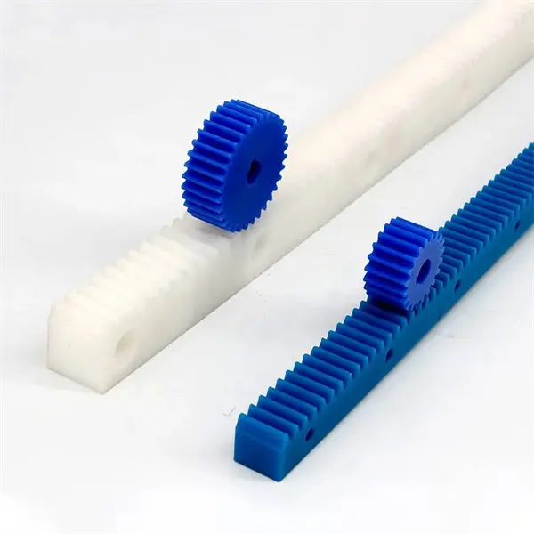
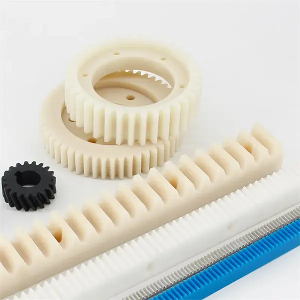
In a rack and pinion setup, there are two primary components that make up the mechanism: the rack and the pinion gear. Here’s a detailed explanation of each component:
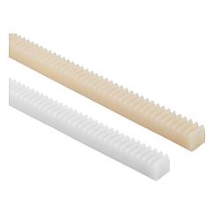
- Rack: The rack is a straight bar with teeth cut along its length. It resembles a gear but in a linear form. The rack is typically a long, narrow strip made of metal or a durable engineering plastic. The teeth on the rack are evenly spaced and have a specific profile that allows them to mesh with the teeth on the pinion gear. The rack can be stationary, meaning it remains fixed in place, or it can move linearly in response to the rotational motion of the pinion gear.
- Pinion Gear: The pinion gear is a small circular gear with teeth that mesh with the teeth on the rack. It is usually mounted on a rotating shaft, such as a motor shaft or an actuator. When rotational force is applied to the pinion gear, it rotates, causing the teeth on the pinion to engage with the teeth on the rack. The pinion gear transfers its rotational motion to the rack, resulting in linear motion. The size and design of the pinion gear, including the number and shape of its teeth, are chosen based on the specific application requirements.
Together, the rack and pinion gear form a mechanical linkage that converts rotational motion into linear motion. As the pinion gear rotates, its teeth push against the teeth on the rack, causing the rack to move linearly. This linear motion can be harnessed for various applications, such as steering systems, robotic arms, linear actuators, and other mechanisms that require controlled linear movement.
In summary, the rack and pinion setup consists of a rack, a straight bar with teeth, and a pinion gear, a small circular gear. These two components work together to enable the conversion of rotational motion into linear motion, offering a versatile and efficient solution for various mechanical systems.


editor by CX 2023-09-08